- 您现在的位置:买卖IC网 > Sheet目录19086 > LML-6LVN-WSP (Dialight)POWERWHITE MODULE LV NW SPOT
�� �
�
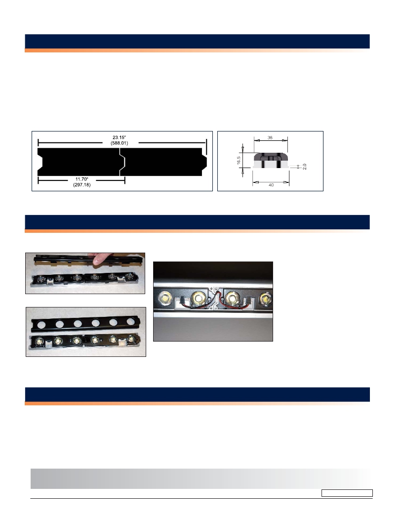
�MECHANICAL� DIMENSIONS�
�11.7”� x� 1.498”� x� 0.585”�
�(297.18mm� x� 38.05mm� x� 14.86mm)�
�Mounting� hole� spacing� =� 3.22”� [81.8mm].�
�Max� screw� size� #8�
�Total� length� for� “Z”� units� connected� end� to� end� =�
�(Z� x� 11.7)� -� ((Z-1)� x� 0.25)� (inches)�
�(Z� x� 297.2)� -� ((Z-1)� x� 6.35)� (mm)�
�Top� View�
�Side� View�
�Example:� 2� units� total� length� =� 23.15”� [588.01]�
�ASSEMBLY� INFORMATION�
�1)� Remove� cover� from�
�module� (Do� not� remove� mask)�
�2)� Connect� LML6-LV-M2M-CAB� quick�
�connect� cables� between� modules� as�
�indicated� in� the� photo.� If� desired,� insert�
�8/32� or� M6� mounting� screws� in� holes�
�provided.�
�3)� Wire� between� cables� may� be� routed�
�through� end� as� indicated� in� photo� or�
�around� side� of� module.�
�4)� Connect� LML6-LV-CON-CAB� into� front�
�of� first� module.�
�5)� Replace� cover.�
�6)� Connect� leads� on� LML6-LV-CON-CAB�
�to� low� voltage� power� supply.�
�Red� wire� to� +,� black� wire� to� -�
�PHOTOMETRIC� DATA�
�IES� 32� files� available,� consult� factory�
�Dialight� reserves� the� right� to� make� changes� at� any� time� in� order� to� supply� the� best� product� possible.�
�The� most� current� version� of� this� document� will� always� be� available� at:�
�www.dialight.com/Assets\Brochures_And_Catalogs\Illumination\MDEXLUMPWMLV.pdf�
�MDEXLUMPWMLV_C�
�www.dialight.com�
�2�
�发布紧急采购,3分钟左右您将得到回复。
相关PDF资料
78C08RAT
SWITCH DIP RAISE SLIDE 8POS
LML-6LVN-WOV
POWERWHITE MODULE LV NW OVAL
LML-6LVN-WMD
POWERWHITE MODULE LV NW MED
553-0744
LED 2HI 3MM YEL/GRN BICLR PC MNT
3020-01097-0
SHUNT CURRENT DC 5A/50MV
PWA-RC1W-WSP
PWAR WARM WHITE SPOT
553-0711
LED 2HI 3MM RED/GRN BICLR PC MNT
78C07RAT
SWITCH DIP RAISE SLIDE 7POS
相关代理商/技术参数
LML6-LV-NW-SP
功能描述:ENG POWERWHITE NEUTRL WHITE SPOT RoHS:是 类别:光电元件 >> LED - 高亮度电源模块 系列:POWERWHITE LV 标准包装:36 系列:5027 TFFC STAR K2 颜色:暖白色 配置:星形 在特定电流下的光通量 - 测试:75lm 电流 - 测试:350mA 电流 - 最大:1.5A 带连接器:无 驱动器电路:无 波长:- 电压:-
LML6LVNWWD
制造商:Dialight 功能描述:ENG POWERWHITE NEUTRL WHITE WIDE
LML-6LVN-WWD
功能描述:POWERWHITE MODULE LV NW WIDE RoHS:是 类别:光电元件 >> LED - 高亮度电源模块 系列:LML 标准包装:36 系列:5027 TFFC STAR K2 颜色:暖白色 配置:星形 在特定电流下的光通量 - 测试:75lm 电流 - 测试:350mA 电流 - 最大:1.5A 带连接器:无 驱动器电路:无 波长:- 电压:-
LML6-LV-NW-WD
功能描述:ENG POWERWHITE NEUTRL WHITE WIDE RoHS:是 类别:光电元件 >> LED - 高亮度电源模块 系列:POWERWHITE LV 标准包装:36 系列:5027 TFFC STAR K2 颜色:暖白色 配置:星形 在特定电流下的光通量 - 测试:75lm 电流 - 测试:350mA 电流 - 最大:1.5A 带连接器:无 驱动器电路:无 波长:- 电压:-
LML-6LVN-WXX
功能描述:POWERWHITE MODULE LV NW N/O RoHS:是 类别:光电元件 >> LED - 高亮度电源模块 系列:LML 标准包装:36 系列:5027 TFFC STAR K2 颜色:暖白色 配置:星形 在特定电流下的光通量 - 测试:75lm 电流 - 测试:350mA 电流 - 最大:1.5A 带连接器:无 驱动器电路:无 波长:- 电压:-
LML-6LVW-WFR
功能描述:POWERWHITE MODULE LV WW FRST RoHS:是 类别:光电元件 >> LED - 高亮度电源模块 系列:LML 标准包装:36 系列:5027 TFFC STAR K2 颜色:暖白色 配置:星形 在特定电流下的光通量 - 测试:75lm 电流 - 测试:350mA 电流 - 最大:1.5A 带连接器:无 驱动器电路:无 波长:- 电压:-
LML6-LV-WW-FR
制造商:DIALIGHT 制造商全称:Dialight Corporation 功能描述:LINEAR MODULES
LML6LVWWMD
制造商:Dialight 功能描述:ENG POWERWHITE WARM WHITE MED